
IGCSE · Physics · Past papers · Paper 2 (Theory)
IGCSE Physics Electric Circuits: Paper 2 Worked Solutions
Opens inside this page. Prefer your own PDF app? Open the PDF.
Full text of IGCSE Physics Electric Circuits: Paper 2 Worked Solutions
www.megalecture.com · www.youtube.com/@megalecture
Online tutoring for Cambridge IGCSE, O Level & A Level Physics
Fahad H. Ahmad
Contact: +92 323 509 4443
M.Eng NUS Singapore · B.Eng NUST · 15+ years of teaching experience in Singapore, UAE & Pakistan · 60,000+ subscribers and 20 million+ video lecture views.
www.Megalecture.com · +92 323 509 4443
IGCSEPHYSICS0625·TOPICALPASTPAPERS
Electric Circuits — Paper 2
Worked Solutions (Theory / Structured)
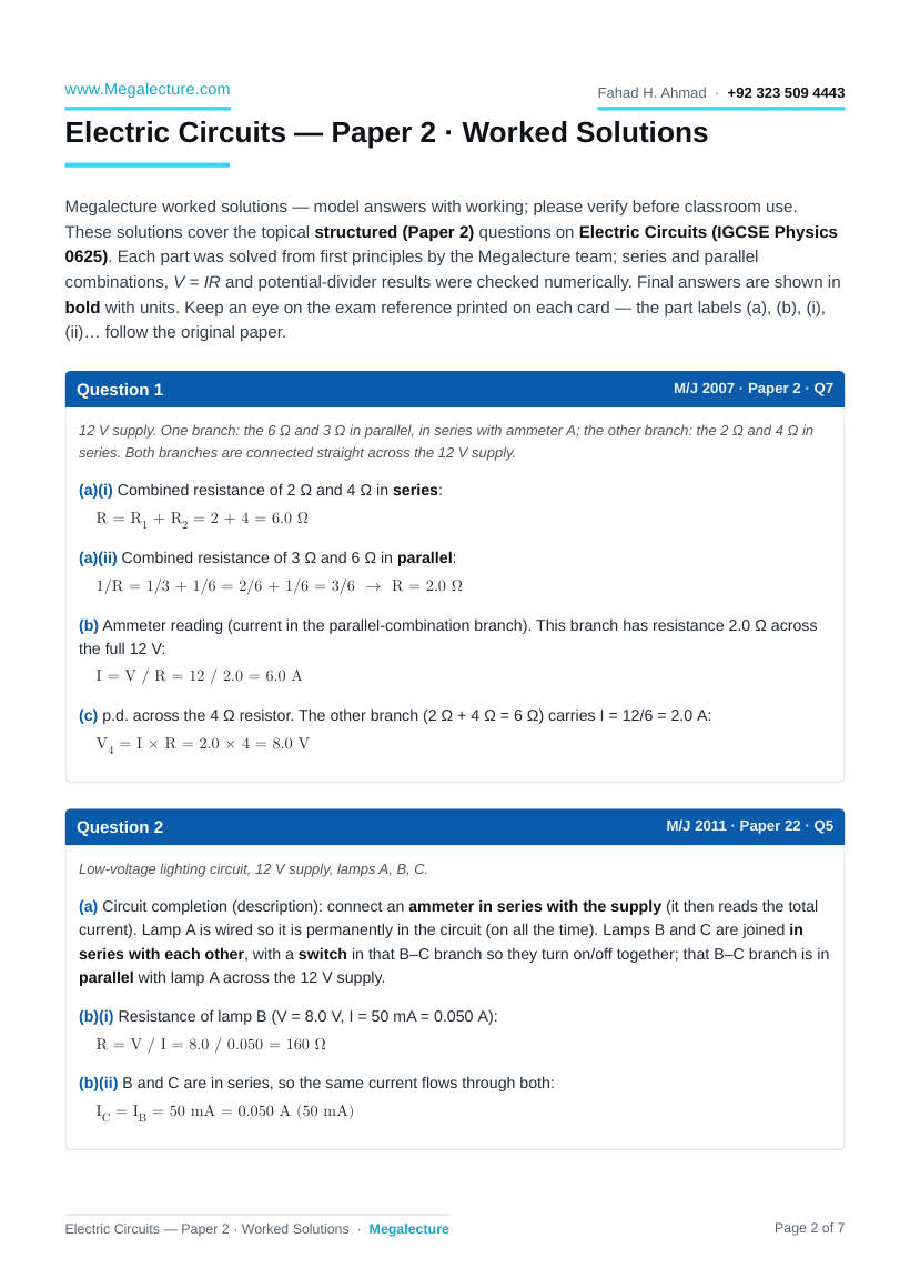
Electric Circuits — Paper 2 · Worked Solutions
Megalecture worked solutions — model answers with working; please verify before classroom use.
These solutions cover the topical structured (Paper 2) questions on Electric Circuits (IGCSE Physics
0625). Each part was solved from first principles by the Megalecture team; series and parallel combinations, V = IR and potential-divider results were checked numerically. Final answers are shown in bold with units. Keep an eye on the exam reference printed on each card — the part labels (a), (b), (i),
(ii)… follow the original paper.
Question 1
12 V supply. One branch: the 6 Ω and 3 Ω in parallel, in series with ammeter A; the other branch: the 2 Ω and 4 Ω in series. Both branches are connected straight across the 12 V supply.
(a)(i) Combined resistance of 2 Ω and 4 Ω in series:
R = R1 + R2 = 2 + 4 = 6.0 Ω
(a)(ii) Combined resistance of 3 Ω and 6 Ω in parallel:
1/R = 1/3 + 1/6 = 2/6 + 1/6 = 3/6 → R = 2.0 Ω
- Ammeter reading (current in the parallel-combination branch). This branch has resistance 2.0 Ω across the full 12 V:
I = V / R = 12 / 2.0 = 6.0 A
- p.d. across the 4 Ω resistor. The other branch (2 Ω + 4 Ω = 6 Ω) carries I = 12/6 = 2.0 A:
V4 = I × R = 2.0 × 4 = 8.0 V
Question 2
Low-voltage lighting circuit, 12 V supply, lamps A, B, C.
- Circuit completion (description): connect an ammeter in series with the supply (it then reads the total current). Lamp A is wired so it is permanently in the circuit (on all the time). Lamps B and C are joined in series with each other, with a switch in that B–C branch so they turn on/off together; that B–C branch is in parallel with lamp A across the 12 V supply.
(b)(i) Resistance of lamp B (V = 8.0 V, I = 50 mA = 0.050 A):
R = V / I = 8.0 / 0.050 = 160 Ω
(b)(ii) B and C are in series, so the same current flows through both:
IC = IB = 50 mA = 0.050 A (50 mA)
M/J 2007 · Paper 2 · Q7
M/J 2011 · Paper 22 · Q5 www.Megalecture.com Fahad H. Ahmad · +92 323 509 4443
Question 3
18 V supply; fixed resistor R in series with a 50 Ω potentiometer (rheostat/divider) feeding a filament lamp rated 12 V,
0.25 A.
- Ammeter (A) is placed in series in the main line carrying the lamp current; voltmeter (V) is connected in parallel across the filament lamp.
- Including R limits the current and lets a p.d. be dropped across it, so the voltage across the lamp can be varied down from 18 V to 0 (and R protects the lamp from excessive current near the top of the range). R acts as a protective/limiting series resistor and shares the supply voltage.
(c)(i) Graph for the filament lamp: a curve through the origin that bends towards the voltage axis as V rises (current rises less steeply at higher voltage), reaching 0.25 A at 12 V — resistance increases as the filament heats up.
(c)(ii) The fixed resistor gives a straight line through the origin (constant resistance, obeys Ohm’s law at constant temperature), whereas the filament-lamp line curves (resistance increases with temperature).
Fixed resistor: linear; lamp: curved.
(d)(i) Current in the 50 Ω resistor. The lamp (12 V) is connected across the lower part of the divider, so the full 50 Ω element has 12 V across it:
I50 = V / R = 12 / 50 = 0.24 A
(d)(ii) Current in R = current from the supply = current in 50 Ω element + lamp current:
IR = 0.24 + 0.25 = 0.49 A
(d)(iii) p.d. across R = supply − lamp voltage:
VR = 18 − 12 = 6.0 V
(d)(iv) Resistance of R:
R = VR / IR = 6.0 / 0.49 = 12 Ω (12.2 Ω)
M/J 2014 · Paper 22 · Q11 www.Megalecture.com Fahad H. Ahmad · +92 323 509 4443
Question 4
6.0 V supply with a 60 Ω resistor and lamp L (rated 6.0 V, 0.90 W) connected in parallel, so each has the full 6.0 V across it.
(a)(i) Current in the 60 Ω resistor:
I = V / R = 6.0 / 60 = 0.10 A
(a)(ii) Current in the power supply = resistor current + lamp current. Lamp current = P / V = 0.90 / 6.0 =
0.15 A:
Isupply = 0.10 + 0.15 = 0.25 A
(b)(i) New circuit: the second lamp is in series with the 60 Ω resistor, and this series combination is connected in parallel with lamp L across the supply. (Battery — then two parallel branches: branch 1 = lamp L; branch 2 = 60 Ω in series with the second lamp.)
(b)(ii) The second lamp is in series with the 60 Ω resistor, so the resistor drops part of the 6.0 V; the second lamp therefore gets less voltage and a smaller current than lamp L (which has the full 6.0 V), so it dissipates less power and is dimmer.
Question 5
Battery with a 1000 Ω fixed resistor in series with a variable resistor R (single loop / series circuit).
(a)(i) In a series circuit the current is the same everywhere:
IB = I1 = I2
(a)(ii) The supply p.d. is shared between the two series resistors:
VB = V1 + V2
- Current in R, with VB = 9.0 V and total resistance = 1000 + 500 = 1500 Ω:
I = V / Rtotal = 9.0 / 1500 = 6.0 × 10⁻³ A (6.0 mA)
M/J 2015 · Paper 21 · Q6
M/J 2016 · Paper 21 · Q8 www.Megalecture.com Fahad H. Ahmad · +92 323 509 4443
Question 6
A 20 Ω resistor in series with a parallel pair (20 Ω and 40 Ω).
- Total resistance. First the parallel pair:
1/RP = 1/20 + 1/40 = 2/40 + 1/40 = 3/40 → RP = 40/3 = 13.3 Ω
Rtotal = 20 + 13.3 = 33 Ω (33.3 Ω)
- Comparing the voltmeter readings: the same current flows through the single 20 Ω resistor (V1) and into the parallel section. The two parallel resistors have the same p.d. across them, so V2 = V3. Since the parallel combination (13.3 Ω) is smaller than 20 Ω, it drops less voltage, so:
V1 is the largest; V2 = V3 (both smaller and equal).
Question 7
Battery with a 10 Ω resistor in series with a 40 Ω resistor (single loop). p.d. across the 40 Ω resistor = 9.6 V.
- Potential difference across a resistor is the work done (energy transferred) per unit charge as charge passes through the resistor (electrical energy converted to other forms per coulomb).
(b)(i) Current in the 40 Ω resistor:
I = V / R = 9.6 / 40 = 0.24 A
(b)(ii) Series circuit, so I = 0.24 A everywhere. p.d. across 10 Ω = 0.24 × 10 = 2.4 V. e.m.f. = sum of p.d.s:
e.m.f. = 9.6 + 2.4 = 12 V
- Best voltmeter for measuring 9.6 V: the 0–20 V meter. The 0–2 V range is too small (9.6 V is off-scale);
the 0–200 V range would put the reading near the bottom of the scale, giving poor precision. 9.6 V sits well across the 0–20 V scale. Choose the 0–20 V voltmeter.
(d)(i) Power produced in the 10 Ω resistor:
P = I2R = (0.24)2 × 10 = 0.58 W (0.576 W)
(d)(ii) A resistor rated ½P (about 0.29 W) is not suitable because the actual power dissipated (0.58 W) exceeds its rating, so it would overheat / be damaged. Power dissipated > rating, so it overheats.
- When resistor R is added in parallel with the 40 Ω resistor:
- Current in 10 Ω resistor — increases: the parallel pair (40 Ω ∥ R) has a smaller resistance than 40 Ω alone, so the total resistance of the circuit falls and the supply current rises.
- p.d. across 10 Ω resistor — increases: larger current through the unchanged 10 Ω gives a larger V = IR across it.
- p.d. across 40 Ω resistor — decreases: the supply e.m.f. is fixed, so as the 10 Ω takes more voltage, less is left across the parallel section.
M/J 2017 · Paper 21 · Q5
M/J 2018 · Paper 22 · Q10 www.Megalecture.com Fahad H. Ahmad · +92 323 509 4443
Question 8
Motorcycle battery = six 2.0 V cells in series. Headlight has two identical filament lamps F and G in parallel; F always lit, G switched by D. With D open the battery supplies 4.6 A.
- Total e.m.f. of six 2.0 V cells in series:
e.m.f. = 6 × 2.0 = 12 V
- Completing the table (Fig. 7.2):
- Switch D open: only F is on. Battery current = current in F = 4.6 A; current in G = 0 A.
- Switch D closed: G (identical, in parallel) now carries the same current as F. Current in F = 4.6 A;
current in G = 4.6 A; battery current = 4.6 + 4.6 = 9.2 A.
- Energy supplied when charge Q = 200 C moves through the circuit (E = QV, with V = e.m.f. = 12 V):
E = Q × V = 200 × 12 = 2400 J
Question 9
A 600 Ω resistor in series with a thermistor, an ammeter and a 20 V d.c. supply; a voltmeter is in parallel with the
600 Ω resistor. Ammeter reads 0.025 A.
(a)(i) Voltmeter reading = p.d. across the 600 Ω resistor:
V = I × R = 0.025 × 600 = 15 V
(a)(ii) p.d. across the thermistor = 20 − 15 = 5.0 V (series), so:
Rthermistor = V / I = 5.0 / 0.025 = 200 Ω
(b)(i) As temperature rises, the resistance of the thermistor decreases.
(b)(ii) Lower total resistance → larger current, so the ammeter reading increases; the larger current through the fixed 600 Ω gives a larger V = IR, so the voltmeter reading increases. Both readings increase.
O/N 2008 · Paper 2 · Q7
O/N 2012 · Paper 21 · Q8 www.Megalecture.com Fahad H. Ahmad · +92 323 509 4443
Question 10
A 2.0 V battery is made from two 2.0 V cells in parallel. The battery, an ammeter, a 2.0 Ω resistor and a parallel pair
(3.0 Ω and X) form a series loop. The 3.0 Ω resistor and X have a combined (parallel) resistance of 2.0 Ω.
(a)(i) Electromotive force (e.m.f.) is the energy converted from other forms to electrical energy per unit charge driven round the circuit by the source (electrical work done per coulomb by the cell).
(a)(ii) Two cells in parallel can supply a larger current / last longer (lower internal resistance) than a single cell, while keeping the same 2.0 V. Larger maximum current / longer life.
(b)(i) Total resistance = 2.0 Ω (single) + 2.0 Ω (parallel combination):
Rtotal = 2.0 + 2.0 = 4.0 Ω
(b)(ii) Resistance of X, from the parallel pair (3.0 Ω ∥ X = 2.0 Ω):
1/X = 1/2.0 − 1/3.0 = 3/6 − 2/6 = 1/6 → X = 6.0 Ω
(c)(i) Ammeter reading (current from the 2.0 V battery):
I = V / Rtotal = 2.0 / 4.0 = 0.50 A
(c)(ii) The current is 0.50 A, so a suitable meter range is 0–1 A (gives a near mid-scale reading).
- X is in parallel with the 3.0 Ω resistor, so the main current splits between them and recombines:
IX = I2 − I3 (equivalently I2 = I3 + IX, where I2 is the current in the 2.0 Ω / main line)
(e)(i) p.d. across the 2.0 Ω resistor (I = 0.50 A):
V = I × R = 0.50 × 2.0 = 1.0 V
(e)(ii) p.d. across the 3.0 Ω resistor = p.d. across the parallel combination = total − 2.0 Ω drop:
V = 2.0 − 1.0 = 1.0 V (= I × Rparallel = 0.50 × 2.0)
(f)(i) Reducing the supply from 12 V to 6.0 V dims the metal-filament lamp, so the filament is cooler; for a metal filament a lower temperature means a lower resistance. Resistance decreases (filament cooler).
(f)(ii) If resistance stayed constant the current would halve to 0.75 A; but the resistance actually falls, so the current does not drop as far. The new reading is therefore greater than 0.75 A.
Note from Megalecture. These are original Megalecture worked solutions prepared for revision use. Numerical answers were verified for series/parallel combinations, V = IR and potential-divider relations. Where an answer depends on circuit interpretation (for example the potential-divider current in Question 3, taken here as the full-element current
12 V / 50 Ω = 0.24 A), an alternative reading may change the figure slightly — please verify against the official mark scheme before classroom use.
O/N 2014 · Paper 21 · Q11 www.Megalecture.com Fahad H. Ahmad · +92 323 509 4443
