
IGCSE · Physics · Past papers · Paper 2 (Theory)
IGCSE Physics Electric Current: Paper 2 Worked Solutions
Opens inside this page. Prefer your own PDF app? Open the PDF.
Check yourself
5 quick questions on IGCSE Physics
Tap an answer to see if you are right, and why. Free, no sign-up.
Start the free test14 of 15 students found these notes useful · 3.7 out of 5 from 3 ratings
Was this note useful?
Full text of IGCSE Physics Electric Current: Paper 2 Worked Solutions
www.megalecture.com · www.youtube.com/@megalecture
Online tutoring for Cambridge IGCSE, O Level & A Level Physics
Fahad H. Ahmad
Contact: +92 323 509 4443
M.Eng NUS Singapore · B.Eng NUST · 15+ years of teaching experience in Singapore, UAE & Pakistan · 60,000+ subscribers and 20 million+ video lecture views.
www.Megalecture.com · +92 323 509 4443
IGCSEPHYSICS0625·TOPICALPASTPAPERS
Electric Current — Paper 2
Worked Solutions (Theory / Structured)
Electric Current — Paper 2 · Worked Solutions
Megalecture worked solutions — model answers with working; please verify before classroom use.
These solutions for the topical structured compilation on Electric Current (IGCSE Physics 0625, Paper
- were prepared from first principles by the Megalecture team. Calculations use the standard relations
Q = It, V = IR, E = QV and the series/parallel rules for cells and resistors, with data taken from each figure as given.
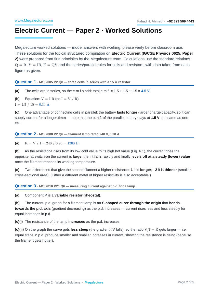
Question 1 · M/J 2005 P2 Q8 — three cells in series with a 15 Ω resistor
(a)
The cells are in series, so the e.m.f.s add: total e.m.f. = 1.5 + 1.5 + 1.5 = 4.5 V.
(b)
Equation: V = I R (so I = V / R).
I = 4.5 / 15 = 0.30 A.
(c)
One advantage of connecting cells in parallel: the battery lasts longer (larger charge capacity, so it can supply current for a longer time) — note that the e.m.f. of the parallel battery stays at 1.5 V, the same as one cell.
Question 2 · M/J 2008 P2 Q6 — filament lamp rated 240 V, 0.20 A (a)
R = V / I = 240 / 0.20 = 1200 Ω.
(b)
As the resistance rises from its low cold value to its high hot value (Fig. 6.1), the current does the opposite: at switch-on the current is large, then it falls rapidly and finally levels off at a steady (lower) value once the filament reaches its working temperature.
(c)
Two differences that give the second filament a higher resistance: 1 it is longer; 2 it is thinner (smaller cross-sectional area). (Either a different metal of higher resistivity is also acceptable.)
Question 3 · M/J 2010 P21 Q6 — measuring current against p.d. for a lamp
(a)
Component P is a variable resistor (rheostat).
(b)
The current–p.d. graph for a filament lamp is an S-shaped curve through the origin that bends towards the p.d. axis (gradient decreasing) as the p.d. increases — current rises less and less steeply for equal increases in p.d.
(c)(i) The resistance of the lamp increases as the p.d. increases.
(c)(ii) On the graph the curve gets less steep (the gradient I/V falls), so the ratio V/I = R gets larger — i.e.
equal steps in p.d. produce smaller and smaller increases in current, showing the resistance is rising (because the filament gets hotter).
www.Megalecture.com Fahad H. Ahmad · +92 323 509 4443
Question 4 · M/J 2013 P21 Q6 — current–p.d. graph for a metal wire (a)
Ohm's law: the current through a metallic conductor is directly proportional to the potential difference across it, provided the temperature (and other physical conditions) stay constant.
(b)
Read a point on the straight line, e.g. p.d. = 4.0 V gives current = 0.20 A.
R = V / I = 4.0 / 0.20 = 20 Ω.
(c)(i) Same metal and same length, but half the cross-sectional area. Resistance is inversely proportional to area, so halving the area doubles the resistance: Rnew = 2 × 20 = 40 Ω.
(c)(ii) The new wire has twice the resistance, so for any p.d. it carries half the current. Draw a straight line through the origin with half the gradient of the original — e.g. passing through (5.0 V, 0.125 A) instead of
(5.0 V, 0.25 A).
Question 5 · M/J 2014 P21 Q11 — torch lamp, four 1.5 V cells in series
(a)(i) Potential difference across the lamp is the work done (energy converted) per unit charge passing through the lamp (1 V = 1 J/C).
(a)(ii).1 The graph is a curve (not a straight line through the origin), so current is not proportional to p.d. — equal increases in p.d. give smaller increases in current.
(a)(ii).2 As the current increases the filament gets hotter, so its resistance increases, which holds the current back below a proportional value.
(a)(iii).1 From Fig. 11.1 at p.d. = 6.0 V the current ≈ 350 mA = 0.35 A.
(a)(iii).2 Q = I t = 0.35 × (2.0 × 3600) = 0.35 × 7200 = 2520 C (≈ 2.5 × 10³ C).
(a)(iii).3 Energy supplied E = Q V = V I t = 6.0 × 2520 = 15 120 J (≈ 1.5 × 10⁴ J).
(a)(iii).4 It is only an estimate because the current is not constant over the 2.0 hours (the cells run down, so the p.d. and current fall) — 0.35 A is only an average/initial value.
(b)
Two cells in parallel can supply the same current for a longer time (more charge stored), while still giving the same e.m.f. of 1.5 V as a single cell.
(c)
The LED needs 3.0 V, so use two cells in series (1.5 + 1.5 = 3.0 V), and connect two such series-pairs in parallel. Circuit: the two parallel branches, a switch and the LED all in one series loop, with the LED connected the correct way round (forward-biased).
www.Megalecture.com Fahad H. Ahmad · +92 323 509 4443
Question 6 · M/J 2019 P21 Q5 — investigating a resistor R (a)
Adjust the variable resistor to change the current; for each setting record the matching ammeter and voltmeter readings, giving a range of values.
(b)(i) Ohm's law: the current in a metallic conductor is directly proportional to the p.d. across it, provided the temperature stays constant.
(b)(ii) Work out V/I for each row (convert mA to A):
V / V I / A R = V/I / Ω
7.6 0.320 23.8
5.2 0.220 23.6
2.4 0.100 24.0
The ratio V/I is constant (≈ 24 Ω), so R is constant — the resistor obeys Ohm's law.
(b)(iii) The currents are a few hundred mA, so choose the 0–200 mA range for the smaller readings
(100 mA), but the largest readings (220 mA and 320 mA) exceed 200 mA, so for those use the 0–10 A range.
In each case pick the smallest range that the reading still fits inside, for the best precision.
Question 7 · O/N 2011 P22 Q6 — measuring p.d. and current for a metal wire
(a)(i) A correct circuit has a cell/battery and switch in the main loop, the metal wire (R) with an ammeter in series with it, and a voltmeter connected in parallel across the wire. (A variable resistor in series lets the current be changed.)
(a)(ii) Close the switch; vary the current (adjust the variable resistor / supply). For each setting read the voltmeter (p.d. across the wire) and the ammeter (current in the wire) and record the pairs of values.
(a)(iii) Defining equation for resistance: R = V / I.
(b)
If V ∝ I then R = V/I is constant, independent of the current. So the graph of resistance against current is a horizontal straight line (parallel to the current axis), not passing through the origin.
Question 8 · O/N 2014 P22 Q7 — three 1.5 V cells in parallel, 6.0 Ω resistor and a resistance wire
(a)(i) One advantage of cells in parallel: the battery lasts longer / can supply current for longer (more charge available), while the e.m.f. stays the same as one cell.
(a)(ii) Cells in parallel give the same e.m.f. as one cell, so the p.d. between P and Q (across the battery) =
1.5 V.
(b)(i) The 6.0 Ω resistor and the wire are in series across 1.5 V with current 0.075 A.
Total resistance Rtotal = V / I = 1.5 / 0.075 = 20 Ω.
Resistance of the wire = Rtotal − 6.0 = 20 − 6.0 = 14 Ω.
(b)(ii) When the wire gets hotter its resistance increases, so the total circuit resistance increases. With the e.m.f. unchanged, I = V/R means the current falls — the ammeter reading decreases.
www.Megalecture.com Fahad H. Ahmad · +92 323 509 4443
Note from Megalecture. Graph readings (Q4, Q5) are taken to the nearest sensible scale division, so the answers carry a small reading uncertainty. These are original Megalecture worked solutions prepared for revision use; please verify against the official mark scheme before classroom use.
www.Megalecture.com Fahad H. Ahmad · +92 323 509 4443
