
A Level · Computer Science · Logic gates and logic circuits: notes and practice
Logic gates and logic circuits: notes and practice
Opens inside this page. Prefer your own PDF app? Open the PDF.
Check yourself
5 quick questions on A Level Computer Science
Tap an answer to see if you are right, and why. Free, no sign-up.
Start the free test3 of 8 students found these notes useful
Was this note useful?
Full text of Logic gates and logic circuits: notes and practice
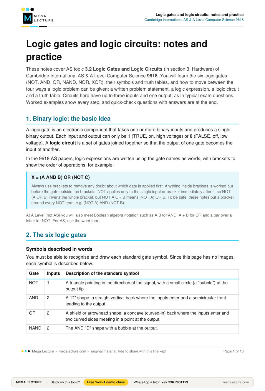
These notes cover AS topic 3.2 Logic Gates and Logic Circuits (in section 3, Hardware) of Cambridge International AS & A Level Computer Science 9618. You will learn the six logic gates (NOT, AND, OR, NAND, NOR, XOR), their symbols and truth tables, and how to move between the four ways a logic problem can be given: a written problem statement, a logic expression, a logic circuit and a truth table. Circuits here have up to three inputs and one output, as in typical exam questions. Worked examples show every step, and quick-check questions with answers are at the end.
1. Binary logic: the basic idea
A logic gate is an electronic component that takes one or more binary inputs and produces a single binary output. Each input and output can only be 1 (TRUE, on, high voltage) or 0 (FALSE, off, low voltage). A logic circuit is a set of gates joined together so that the output of one gate becomes the input of another.
In the 9618 AS papers, logic expressions are written using the gate names as words, with brackets to show the order of operations, for example:
X = (A AND B) OR (NOT C)
Always use brackets to remove any doubt about which gate is applied first. Anything inside brackets is worked out before the gate outside the brackets. NOT applies only to the single input or bracket immediately after it, so NOT (A OR B) inverts the whole bracket, but NOT A OR B means (NOT A) OR B. To be safe, these notes put a bracket around every NOT term, e.g. (NOT A) AND (NOT B).
At A Level (not AS) you will also meet Boolean algebra notation such as A.B for AND, A + B for OR and a bar over a letter for NOT. For AS, use the word form.
2. The six logic gates
Symbols described in words
You must be able to recognise and draw each standard gate symbol. Since this page has no images, each symbol is described below.
| Gate | Inputs | Description of the standard symbol |
|---|---|---|
| NOT | 1 | A triangle pointing in the direction of the signal, with a small circle (a "bubble") at the output tip. |
| AND | 2 | A "D" shape: a straight vertical back where the inputs enter and a semicircular front leading to the output. |
| OR | 2 | A shield or arrowhead shape: a concave (curved-in) back where the inputs enter and two curved sides meeting in a point at the output. |
| NAND | 2 | The AND "D" shape with a bubble at the output. |
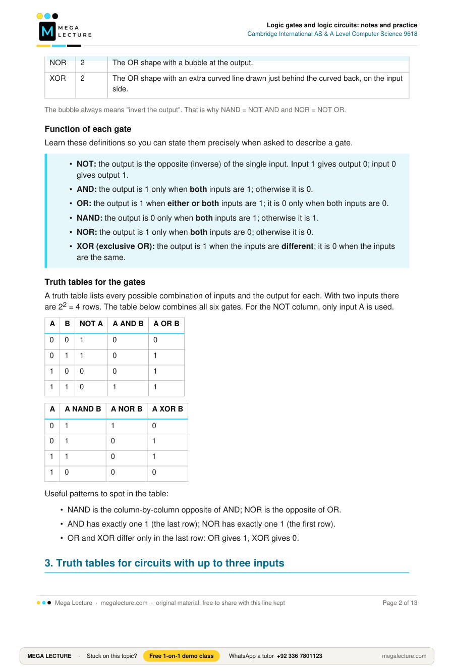
| NOR | 2 | The OR shape with a bubble at the output. |
| XOR | 2 | The OR shape with an extra curved line drawn just behind the curved back, on the input side. |
The bubble always means "invert the output". That is why NAND = NOT AND and NOR = NOT OR.
Function of each gate
Learn these definitions so you can state them precisely when asked to describe a gate.
- NOT: the output is the opposite (inverse) of the single input. Input 1 gives output 0; input 0 gives output 1.
- AND: the output is 1 only when both inputs are 1; otherwise it is 0.
- OR: the output is 1 when either or both inputs are 1; it is 0 only when both inputs are 0.
- NAND: the output is 0 only when both inputs are 1; otherwise it is 1.
- NOR: the output is 1 only when both inputs are 0; otherwise it is 0.
- XOR (exclusive OR): the output is 1 when the inputs are different; it is 0 when the inputs are the same.
Truth tables for the gates
A truth table lists every possible combination of inputs and the output for each. With two inputs there are 22 = 4 rows. The table below combines all six gates. For the NOT column, only input A is used.
| A | B | NOT A | A AND B | A OR B | A NAND B | A NOR B | A XOR B |
|---|---|---|---|---|---|---|---|
| 0 | 0 | 1 | 0 | 0 | 1 | 1 | 0 |
| 0 | 1 | 1 | 0 | 1 | 1 | 0 | 1 |
| 1 | 0 | 0 | 0 | 1 | 1 | 0 | 1 |
| 1 | 1 | 0 | 1 | 1 | 0 | 0 | 0 |
Useful patterns to spot in the table:
- NAND is the column-by-column opposite of AND; NOR is the opposite of OR.
- AND has exactly one 1 (the last row); NOR has exactly one 1 (the first row).
- OR and XOR differ only in the last row: OR gives 1, XOR gives 0.
3. Truth tables for circuits with up to three inputs
For n inputs there are 2n rows, so a three-input circuit needs 23 = 8 rows. Always list the inputs in binary counting order, from 000 to 111. This makes it hard to miss a row and easy for the examiner to mark.
| Row | A | B | C |
|---|---|---|---|
| 0 | 0 | 0 | 0 |
| 1 | 0 | 0 | 1 |
| 2 | 0 | 1 | 0 |
| 3 | 0 | 1 | 1 |
| 4 | 1 | 0 | 0 |
| 5 | 1 | 0 | 1 |
| 6 | 1 | 1 | 0 |
| 7 | 1 | 1 | 1 |
Quick way to fill the input columns: C alternates 0,1,0,1…; B goes in pairs 0,0,1,1…; A goes in fours 0,0,0,0,1,1,1,1.
When a circuit has several gates, add working columns for each intermediate gate output. Work out these columns first, then combine them to get the final output. Exam truth tables often provide a "working space" column for exactly this.
Worked example 1: completing a truth table from an expression
Complete the truth table for X = (A AND B) OR (NOT C).
Step 1: Identify the parts. There are two sub-results: P = A AND B, and Q = NOT C. Then X = P OR Q.
Step 2: Fill the P column: 1 only when A = 1 and B = 1 (rows 6 and 7).
Step 3: Fill the Q column: the opposite of C, so 1 in rows 0, 2, 4, 6.
Step 4: X = P OR Q, so X is 1 wherever P or Q (or both) is 1.
| Row | A | B | C | P = A AND B | Q = NOT C | X = P OR Q |
|---|---|---|---|---|---|---|
| 0 | 0 | 0 | 0 | 0 | 1 | 1 |
| 1 | 0 | 0 | 1 | 0 | 0 | 0 |
| 2 | 0 | 1 | 0 | 0 | 1 | 1 |
| 3 | 0 | 1 | 1 | 0 | 0 | 0 |
| 4 | 1 | 0 | 0 | 0 | 1 | 1 |
| 5 | 1 | 0 | 1 | 0 | 0 | 0 |
| 6 | 1 | 1 | 0 | 1 | 1 | 1 |
| 7 | 1 | 1 | 1 | 1 | 0 | 1 |
Check: X is 0 only when C = 1 and A AND B is 0 (rows 1, 3, 5). This agrees with the table.
4. Writing a logic expression from a circuit
To turn a circuit into an expression, work from the inputs towards the output. Label the output of every gate, write each one as a small expression, then substitute into the next gate.
Worked example 2: circuit to expression
Circuit description: Inputs A and B enter an OR gate. Input C enters a NOT gate. The outputs of the OR gate and the NOT gate enter a NAND gate, whose output is X.
Step 1: Output of the OR gate: A OR B.
Step 2: Output of the NOT gate: NOT C.
Step 3: These two are the inputs to the NAND gate, so put each in brackets: X = (A OR B) NAND (NOT C).
An equally correct answer is X = NOT ((A OR B) AND (NOT C)), because NAND is AND followed by NOT. Unless the question says otherwise, either form gains the marks as long as the brackets are right.
5. Drawing a circuit from an expression
Work the other way round: find the gate that is applied last (the one outside all brackets). That gate is drawn nearest the output. Then draw the gates that feed it, and so on back to the inputs.
Worked example 3: expression to circuit
Draw a logic circuit for X = (A XOR B) AND (NOT (B OR C)).
Step 1: The gate outside the brackets is AND, so the final gate is an AND gate with output X.
Step 2: The first input to the AND gate is A XOR B: draw an XOR gate with inputs A and B.
Step 3: The second input to the AND gate is NOT (B OR C). Draw an OR gate with inputs B and C, followed by a NOT gate. (A single NOR gate with inputs B and C does the same job and would be accepted unless the question limits which gates you may use.)
Step 4: Input B is used twice, so draw a branch from the B line: one wire to the XOR gate and one to the OR gate. Show the join with a dot.
Circuit in words: A and B enter an XOR gate. B (branched) and C enter an OR gate, whose output enters a NOT gate. The XOR output and the NOT output enter an AND gate, whose output is X.
Gates used: 1 XOR, 1 OR, 1 NOT, 1 AND (or 1 XOR, 1 NOR, 1 AND).
Exam tip: the 9618 syllabus notes state that every gate other than NOT has two inputs. Do not draw a three-input AND or OR gate; use two two-input gates instead, e.g. (A AND B) AND C.
6. From a problem statement to expression, circuit and truth table
Real problems are given in words. Follow these steps:
- Match each condition in the statement to an input letter and decide what 1 and 0 mean.
- Look for the key words: "and", "or", "not", "either … but not both" (XOR), "neither … nor" (NOR).
- Group the conditions with brackets to form the expression.
- Draw the circuit from the expression.
- Complete the truth table and check it against the statement row by row.
Common traps
- "Unless" usually means AND NOT: "X is on when A is on, unless B is on" gives X = A AND (NOT B).
- Read the meaning of 1 for each input carefully before you negate it. If D = 1 means "door closed", then "the door is open" is NOT D.
- Draw NOT as a full gate (a triangle with a bubble). A bubble on its own on a wire does not gain the mark.
- A NAND or NOR gate can replace an AND or OR gate followed by NOT only if the question does not restrict which gates you may use.
- Fill in every row of the truth table and every working column, including rows where the output is 0.
Worked example 4: greenhouse vent
Problem statement: The roof vent V of a greenhouse opens (V = 1) when it is daytime and either the temperature is high or the humidity is high.
| Input | Meaning of 1 | Meaning of 0 |
|---|---|---|
| D | it is daytime | it is night |
| T | temperature is high | temperature is not high |
| H | humidity is high | humidity is not high |
Step 1: expression. "Either the temperature … or the humidity" gives T OR H. This must be combined with "daytime" using AND. The brackets matter, because the OR must be worked out first:
V = D AND (T OR H)
Step 2: circuit. T and H enter an OR gate. The OR output and D enter an AND gate, whose output is V.
Step 3: truth table.
| D | T | H | T OR H | V |
|---|---|---|---|---|
| 0 | 0 | 0 | 0 | 0 |
| 0 | 0 | 1 | 1 | 0 |
| 0 | 1 | 0 | 1 | 0 |
| 0 | 1 | 1 | 1 | 0 |
| 1 | 0 | 0 | 0 | 0 |
| 1 | 0 | 1 | 1 | 1 |
| 1 | 1 | 0 | 1 | 1 |
| 1 | 1 | 1 | 1 | 1 |
Step 4: check. At night (first four rows) the vent never opens. In the daytime, it opens if at least one of temperature or humidity is high. This matches the statement.
Common error: writing (D AND T) OR H. That would open the vent at night whenever the humidity is high.
Worked example 5: a problem statement that needs NOT
Problem statement: A water pump P runs (P = 1) if the tank is not full and there is no sensor fault, or if the manual override is on and the tank is not full.
Inputs: L = 1 if the tank is full; M = 1 if the manual override is on; F = 1 if there is a sensor fault.
Step 1: expression. "Tank not full and no fault" is (NOT L) AND (NOT F). "Override on and tank not full" is M AND (NOT L). These are joined by OR:
P = ((NOT L) AND (NOT F)) OR (M AND (NOT L))
Step 2: circuit. L goes into a NOT gate; F goes into a second NOT gate. NOT L and NOT F enter AND gate 1. M and NOT L (a branch from the first NOT gate) enter AND gate 2. The outputs of both AND gates enter an OR gate, whose output is P.
Step 3: truth table (working columns R = (NOT L) AND (NOT F), S = M AND (NOT L)).
| Row | L | M | F | NOT L | NOT F | R | S | P |
|---|---|---|---|---|---|---|---|---|
| 0 | 0 | 0 | 0 | 1 | 1 | 1 | 0 | 1 |
| 1 | 0 | 0 | 1 | 1 | 0 | 0 | 0 | 0 |
| 2 | 0 | 1 | 0 | 1 | 1 | 1 | 1 | 1 |
| 3 | 0 | 1 | 1 | 1 | 0 | 0 | 1 | 1 |
| 4 | 1 | 0 | 0 | 0 | 1 | 0 | 0 | 0 |
| 5 | 1 | 0 | 1 | 0 | 0 | 0 | 0 | 0 |
| 6 | 1 | 1 | 0 | 0 | 1 | 0 | 0 | 0 |
| 7 | 1 | 1 | 1 | 0 | 0 | 0 | 0 | 0 |
Check: the pump never runs when the tank is full (L = 1, rows 4 to 7), which makes sense. With a fault and no override (row 1) it stays off; the override lets it run despite the fault (row 3).
7. From a truth table to an expression and a circuit
If you are given a truth table and asked for an expression, use the sum-of-products method:
- Find every row where the output is 1.
- For each such row, write the inputs joined by AND, putting NOT in front of any input that is 0 in that row.
- Join all these row terms with OR.
To build a circuit from a truth table, first write the expression this way, then draw the circuit from the expression, using only two-input gates.
Worked example 6: truth table to expression and circuit
A circuit has output X = 1 only in the rows A, B, C = 011, 101 and 110 (that is, exactly two inputs are 1).
Step 1: one term for each row where X = 1.
Row 011: A is 0, B and C are 1 → ((NOT A) AND B AND C)
Row 101: B is 0 → (A AND (NOT B) AND C)
Row 110: C is 0 → (A AND B AND (NOT C))
Step 2: join the terms with OR.
X = ((NOT A) AND B AND C) OR (A AND (NOT B) AND C) OR (A AND B AND (NOT C))
Check each term: it is 1 for its own row only, so OR-ing them gives 1 in exactly the three required rows.
Step 3: circuit. Each gate other than NOT may have only two inputs. So each three-input AND becomes two two-input ANDs, e.g. ((NOT A) AND B) AND C, and the three terms are joined by two OR gates: (T1 OR T2) OR T3.
- A goes into NOT gate 1, B into NOT gate 2, C into NOT gate 3.
- Term 1: NOT A and B enter AND gate 1; the output of AND gate 1 and C enter AND gate 2.
- Term 2: A and NOT B enter AND gate 3; the output of AND gate 3 and C enter AND gate 4.
- Term 3: A and B enter AND gate 5; the output of AND gate 5 and NOT C enter AND gate 6.
- The outputs of AND gates 2 and 4 enter OR gate 1. The output of OR gate 1 and the output of AND gate 6 enter OR gate 2, whose output is X.
Gates used: 3 NOT, 6 AND, 2 OR. Each input is branched to every gate that uses it.
8. Equivalent circuits and simplification
Two circuits are logically equivalent if they give the same output for every combination of inputs. At AS you prove this by completing a truth table for each and comparing the output columns; you are not expected to use Boolean algebra laws. Formal simplification using Boolean algebra laws and Karnaugh maps is an A Level topic, so it is not required at AS, but a few facts (each of which you can check with a truth table) help you spot shortcuts:
| Expression | Equivalent to | Why |
|---|---|---|
| NOT (NOT A) | A | Inverting twice returns the original value. |
| NOT (A AND B) | A NAND B | Definition of NAND. |
| NOT (A OR B) | A NOR B, also (NOT A) AND (NOT B) | Output is 1 only when both inputs are 0. |
| NOT (A AND B) | (NOT A) OR (NOT B) | Output is 0 only when both inputs are 1. |
| (A AND (NOT B)) OR ((NOT A) AND B) | A XOR B | 1 only when the inputs differ. |
| A AND A; A OR A | A | Combining an input with itself changes nothing. |
Extension (beyond AS): NAND and NOR are called universal gates: any circuit can be built using only NAND gates (or only NOR gates). For example, A NAND A = NOT A. To make A AND B from NANDs only, feed A and B into a NAND gate, then feed its output into both inputs of a second NAND gate; the second gate acts as a NOT, giving NOT (A NAND B) = A AND B.
Key terms
| Term | Definition |
|---|---|
| Logic gate | An electronic component that performs a Boolean operation on one or more binary inputs to give one binary output. |
| Logic circuit | A combination of logic gates connected together to carry out a more complex function. |
| Truth table | A table showing the output of a gate or circuit for every possible combination of inputs. |
| Logic expression | A written statement of a circuit's function using inputs, gate names and brackets, e.g. X = A AND (B OR C). |
| Problem statement | A description in words of the conditions under which an output should be 1. |
| Working column | An extra column in a truth table holding the output of an intermediate gate. |
| Sum of products | An expression made by AND-ing the inputs for each row where the output is 1, then OR-ing these terms together. |
| Inverter | Another name for a NOT gate. |
| Exclusive OR (XOR) | A gate whose output is 1 when its two inputs are different. |
| Logically equivalent | Describes two circuits or expressions that produce identical outputs for all input combinations. |
| Universal gate (extension) | A gate (NAND or NOR) from which every other gate can be built. |
Quick check
- State the output of a NOR gate when both inputs are 0. [1]
- Identify the logic gate whose output is 1 only when its two inputs are different. [1]
- State how many rows are needed in a truth table for a circuit with three inputs, and explain why. [2]
- Describe the function of a NAND gate. [2]
- Complete a truth table for the NAND gate with inputs A and B. [2]
- A circuit is described as follows: inputs A and B enter a NOR gate; the output of the NOR gate and input C enter an AND gate, whose output is X. Write the logic expression for this circuit. [2]
- Complete the truth table for the circuit in question 6. [4]
- Complete the truth table for X = (NOT (A AND B)) XOR C. [4]
- A lift has a warning buzzer W that sounds (W = 1) if the lift is moving and the door is not closed, or if the lift is moving and it is overloaded. The inputs are M (1 = lift moving), C (1 = door closed) and L (1 = lift overloaded).
- Write a logic expression for W. [3]
- Describe the logic circuit for W, naming each gate and its inputs. [3]
In the exam this would be "Draw the logic circuit". Practise by sketching it on paper with the correct gate symbols and only two-input gates (plus NOT). - Complete the truth table for W. [4]
- For inputs A, B, C in the order 000 to 111, a circuit's output X is 0, 1, 0, 0, 0, 1, 1, 0.
- Write a logic expression for X. [3]
- Describe a logic circuit for your expression in (a), using only two-input gates (plus NOT gates). [3]
- Use truth tables to show that NOT (A OR B) is logically equivalent to (NOT A) AND (NOT B). [3]
- Complete a truth table, with working columns, for (A OR B) AND (NOT (A AND B)), and use it to identify the single gate that is equivalent to this expression. [3]
Answers
1. 1.
2. XOR (exclusive OR).
3. 8 rows. Each input can be 0 or 1, so the number of combinations is 2 × 2 × 2 = 23 = 8.
4. A NAND gate has two inputs. Its output is 0 only when both inputs are 1; for every other input combination the output is 1. (It is an AND gate followed by NOT.)
5.
| A | B | X |
|---|---|---|
| 0 | 0 | 1 |
| 0 | 1 | 1 |
| 1 | 0 | 1 |
| 1 | 1 | 0 |
6. X = (A NOR B) AND C (or X = (NOT (A OR B)) AND C).
7. A NOR B is 1 only when A = 0 and B = 0, so X is 1 only in row 001.
| A | B | C | A NOR B | X |
|---|---|---|---|---|
| 0 | 0 | 0 | 1 | 0 |
| 0 | 0 | 1 | 1 | 1 |
| 0 | 1 | 0 | 0 | 0 |
| 0 | 1 | 1 | 0 | 0 |
| 1 | 0 | 0 | 0 | 0 |
| 1 | 0 | 1 | 0 | 0 |
| 1 | 1 | 0 | 0 | 0 |
| 1 | 1 | 1 | 0 | 0 |
8. Working column N = NOT (A AND B), then X = N XOR C.
| A | B | C | N | X |
|---|---|---|---|---|
| 0 | 0 | 0 | 1 | 1 |
| 0 | 0 | 1 | 1 | 0 |
| 0 | 1 | 0 | 1 | 1 |
| 0 | 1 | 1 | 1 | 0 |
| 1 | 0 | 0 | 1 | 1 |
| 1 | 0 | 1 | 1 | 0 |
| 1 | 1 | 0 | 0 | 0 |
| 1 | 1 | 1 | 0 | 1 |
9 (a). W = (M AND (NOT C)) OR (M AND L). One mark for each bracketed term, one for joining them with OR.
Accept any logically equivalent expression, e.g. W = M AND ((NOT C) OR L): 1 mark for M AND …, 1 mark for NOT C, 1 mark for OR L, with the brackets correct.
9 (b). C enters a NOT gate. M and NOT C enter AND gate 1. M (branched) and L enter AND gate 2. The outputs of AND gates 1 and 2 enter an OR gate, whose output is W. (For the shorter expression: NOT C and L enter an OR gate; M and the OR output enter an AND gate, whose output is W.)
9 (c).
| M | C | L | M AND (NOT C) | M AND L | W |
|---|---|---|---|---|---|
| 0 | 0 | 0 | 0 | 0 | 0 |
| 0 | 0 | 1 | 0 | 0 | 0 |
| 0 | 1 | 0 | 0 | 0 | 0 |
| 0 | 1 | 1 | 0 | 0 | 0 |
| 1 | 0 | 0 | 1 | 0 | 1 |
| 1 | 0 | 1 | 1 | 1 | 1 |
| 1 | 1 | 0 | 0 | 0 | 0 |
| 1 | 1 | 1 | 0 | 1 | 1 |
10 (a). The output is 1 in rows 001, 101 and 110.
X = ((NOT A) AND (NOT B) AND C) OR (A AND (NOT B) AND C) OR (A AND B AND (NOT C)).
An equivalent shorter answer, X = ((NOT B) AND C) OR (A AND B AND (NOT C)), is also correct. When you draw either expression, each three-input AND becomes two two-input ANDs, e.g. ((NOT A) AND (NOT B)) AND C, and three terms are joined by two OR gates: (T1 OR T2) OR T3.
10 (b). For the full expression: A, B and C each enter their own NOT gate. NOT A and NOT B enter AND gate 1; its output and C enter AND gate 2. A and NOT B enter AND gate 3; its output and C enter AND gate 4. A and B enter AND gate 5; its output and NOT C enter AND gate 6. The outputs of AND gates 2 and 4 enter OR gate 1; the output of OR gate 1 and the output of AND gate 6 enter OR gate 2, whose output is X. One mark for the correct NOT gates, one for the AND gates (two inputs each), one for the two OR gates combining the terms.
For the shorter expression: B enters NOT gate 1 and C enters NOT gate 2. NOT B and C enter AND gate 1. A and B enter AND gate 2; its output and NOT C enter AND gate 3. The outputs of AND gates 1 and 3 enter an OR gate, whose output is X.
11.
| A | B | A OR B | NOT (A OR B) | NOT A | NOT B | (NOT A) AND (NOT B) |
|---|---|---|---|---|---|---|
| 0 | 0 | 0 | 1 | 1 | 1 | 1 |
| 0 | 1 | 1 | 0 | 1 | 0 | 0 |
| 1 | 0 | 1 | 0 | 0 | 1 | 0 |
| 1 | 1 | 1 | 0 | 0 | 0 | 0 |
The two output columns are identical (1, 0, 0, 0) for every input combination, so the expressions are logically equivalent.
12.
| A | B | A OR B | A AND B | NOT (A AND B) | X |
|---|---|---|---|---|---|
| 0 | 0 | 0 | 0 | 1 | 0 |
| 0 | 1 | 1 | 0 | 1 | 1 |
| 1 | 0 | 1 | 0 | 1 | 1 |
| 1 | 1 | 1 | 1 | 0 | 0 |
The output column (0, 1, 1, 0) is the same as the XOR column, so the single equivalent gate is XOR. (A OR B) is 1 when at least one input is 1; NOT (A AND B) removes the case where both are 1, leaving "1 only when the inputs differ". One mark for the working columns, one for the output column, one for identifying XOR.
